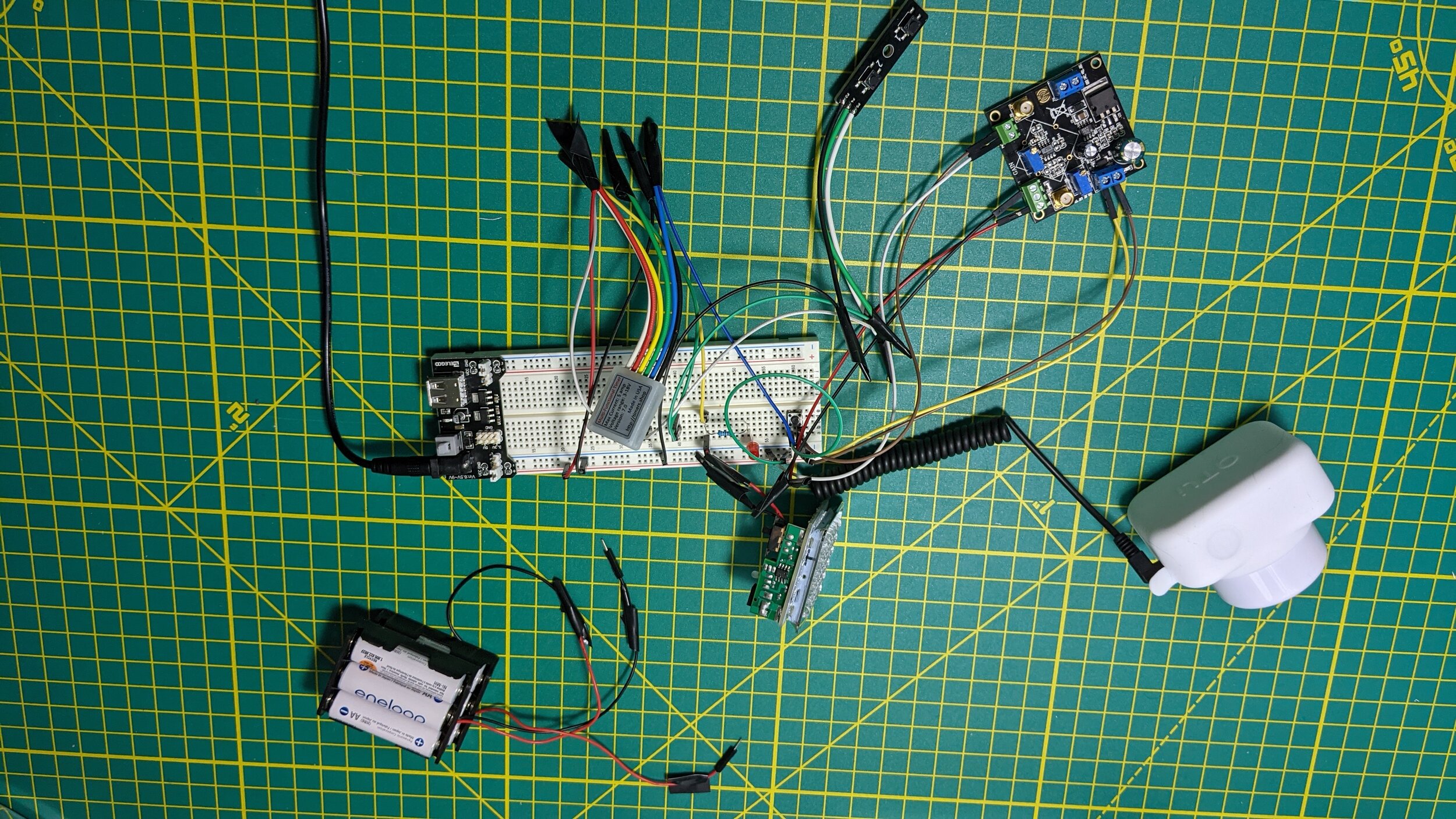
I’m going to call this one a successful failure. I managed to build a circuit that did exactly what I wanted.. Based on the signal from the camera it turned on the IR light source for a predefined period of time and then off again. The problem is that the signal from the camera doesn’t seem to be in sync with the shutter, or this circuit isn’t fast enough, so it doesn’t light the scene when the picture is taken. I tried a couple of other ways to try and make it work to no avail. I even opened up the camera to see if I could find a handy and obvious place to get the right signal. No dice. So, on to plan B which is to build an external battery pack with batteries in parallel that will last the night. I know that’ll work.
The components that I used in this circuit were the following:
Mini Timer Time Delay Relay .1 Sec to 400 days. 3V 12V 18V 5A. Power on or Off Delay, Cycling and More. from the Timers Shop . This is a very cool component that has a microcontroller, a trigger, a timer, and a relay. It has a lot of modes to control the output in different ways, I’m sure I’ll find a use for it again.
Taidacent AD620 High Accuracy Low Cost Low Power Instrumentation Amplifier Voltage Amplifier Module Differential Amplifier Single-ended/Differential Small Signal : I needed this to boost the mV signal from the camera to V so it could trigger the light.
NOYITO Low Voltage MOSFET Switching Module 3V 5V Low Control High Voltage 12V 24V 36V Field Effect Transistor Module: I used this module in the first circuit to trigger the light assuming that the input signal from the camera was on long enough to illuminate things. It basically uses a trigger voltage to turn on another higher voltage circuit.
